A channel map is an image that contains only emission from within a given interval of velocities along the line of sight, i.e. a certain velocity "channel". The channel map display in Shape also supports a light echo mode, which will be explained after the default velocity channel map mode (see below).
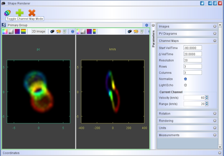
Channel maps are displayed as a mode of the rendering module. You activate the channel map mode by clicking on the icon with the sliced ellipsoid.

The symbol represents the interpretation of the images in a homologously expanding nebula: each channel map is a different slice along the line of sight. For objects with deviations from such an expansion, or rotating objects, such an interpretation is, of course, not possible.
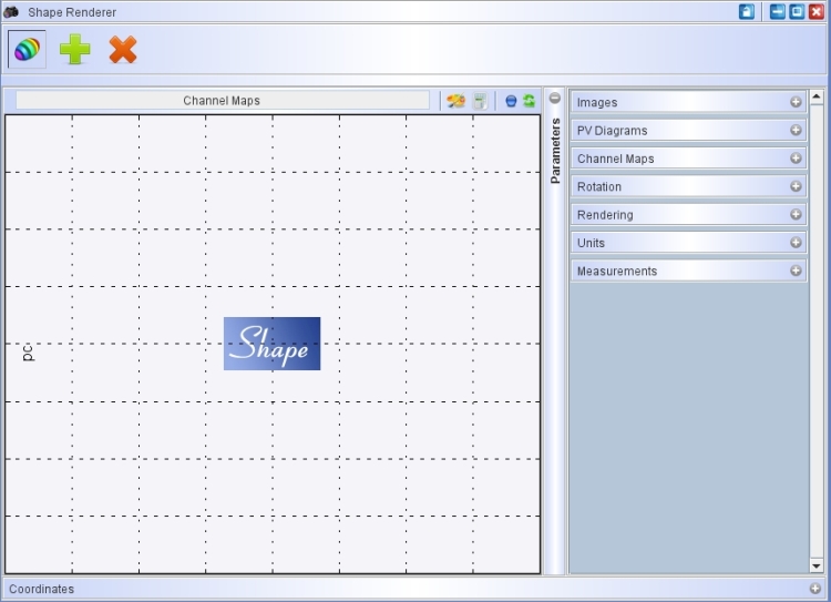
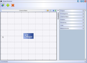
When you first activate the channel map mode the following screen shows (click to see full larger image):
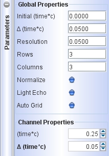
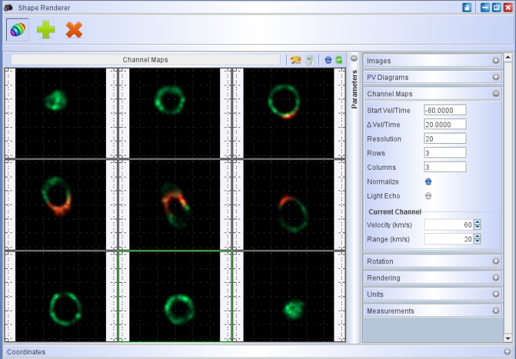
The image and p-v displays have been replaced by the channel map display. To continue with the channel map setup open the Channel Map tab in the Parameters panel on the right. The channel map parameter panel looks as follows:
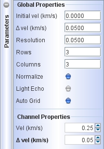
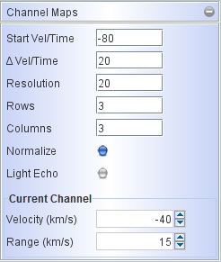
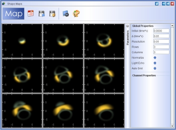
The initial setup is on the left, while the right shows the setup for the 3x3 image display seen below (click on the image for a larger image).
Channel maps are rendered just like normal images by clicking on the large blue Shape button or by using the keyboard short-cut Ctrl-s.
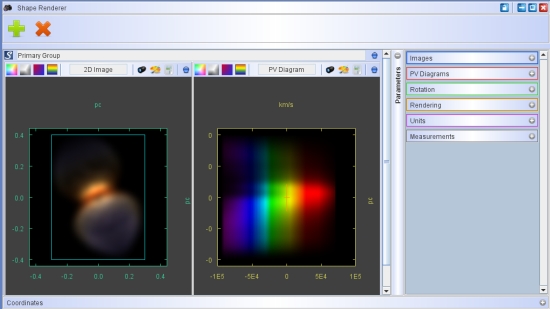
The Start Vel is the central velocity of the channel with the most blue-shifted velocity channel. It is represented in the first channel map at the top left. Each successive channel adds a velocity of Delta Vel going from left to right in a row. The last channel is that in the lower right corner of the array of channel maps. In the example below, in the rendering on the right is the full integrated image and a central P-V diagram with the Doppler-shift color coding. Note that the blue-shifted lobe of the bipolar nebula corresponds to the channel maps at the top of the channel map array. The central velocities coded in green are included in the middel channels and the red-shifted channels are at the bottom.
The Resolution parameter is the full range of velocities around the central velocity, such that the channel maps includes velocities between Vel - Resolution/2 and Vel+Resolution/2. In a model calculation that will be compared with observations, make sure the Resolution is similar to that in the observation. The choice of resolution may dramatically influence the appearance of the channel map image.
The parameters Rows and Columns set the number and arrangment of channels that will be calculated.


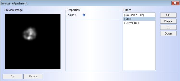
Note that the representation in the channel maps by default shows the objects colored coded as given by the colors in the 3D Module. This help to identify different sub-objects of the model. If you wish to have a grey-scale representation for better comparison with observations, you can add a "Grey" image filter in the Image Adjustment dialog. Open the Image Adjustment dialog by clicking on the color palette icon. Then add a "Grey" filter and move it above the "Normalization" filter. Moving it above the "Normalization" filter makes sure that the normalization is done after the gey-scale is applied. After confirming the adjustment by clicking "OK", the dialog closes. The change is not immediately applied. Rerender to apply the grey-scaling.
Click on the image below to see a higher resolution view of the Image Adjustment dialog.

Lightechoes
The light echo mode is enabled by activating the blue Light Echo button in the Channel Map parameter panel. The setup for light echoes just like that of velocity channel maps. But instead images with a given velocity range, we now have light travel time channels. Actually, the channels are set in terms of distance, which is a more useful physical quantity. So, the channels are in units of the distance in physical units of the images, which can be meters, parsec or angular units like arcsec. For the example above the light echo setup can be seen in the images below. Note the difference in the structure seen in the light echo channels as compared to the velocity channels from above. For a brief description of the physics of a light echo see the theory section on the subject.
Download the sample project for the light echo setup here. You can change it to the velocity channel map example from above by changing the corresponding parameters and disabling the Light Echo button.